
Poly Lines.

Details related to Polylines.

    Polylines are the segment of continous line segments which acts as a same object. you can draw lines, arcs, or combination of both as polylines.

When to Use Polylines:
  • when you want to have vertices as join even after grip editing.
  • Move and copy polyline as single unit.
  • when you want to create a closed loop or open link of line as single object.
  • Easily create rectangles and polygons as single object.
  • Easy extrusion for 3D objects.
Modifying Polylines:

    you can edit poly line by various methods.

Basic procedure to edit poly line is to edit it by using grips. when you select a polyline you can see grips which can be used to edit poly line to move, add, or delete individual points. You can also convert a straight polyline to arc and vice versa by using grips.

You can use PEDIT command to change width of individual segment or entire polyline.

Many options are available in properties pallete which can be edited for poly line.


Line types and polyline vertices:

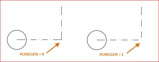
    For polylines, you can specify whether a linetype pattern is centered on each segment or is continuous across vertices throughout the entire length of the polyline.

    Use the PLINEGEN system variable to specify this option for new
objects. You can update existing polylines on the Properties palette in
the Linetype Generation setting.


Comments

Popular posts from this blog

From command

From:  fro (enter) From command is used to draw a line or any objects base point at a specific distance from a particular reference point. (Video link attached at the end of commands)   Command: L LINE Specify first point: fro Base point: Click at corner A <Offset>: 5 Specify next point or [Undo]: fro Base point: Click at corner B  <Offset>: 50 Specify next point or [Undo]: ESC click here to see how to use from command. Related Concepts: About Polyline. About lines. About multilines. Relates Task: How to draw lines. How to draw polylines. How to draw multiline. How to edit multiline. How to create multiline style. Related reference: Commands for linear geometric objects. Mid point command. Co-ordinate entry system. Direct distance entry. How to draw lines with precision.

Co-ordinate systems

Hello Friends,             This is my first blog on AutoCAD tutorials. I won’t waste time on overview of AutoCAD and its uses which everyone knows. I will start directly with Co-ordinate systems of AutoCAD.             Co-ordinates systems are not of more use left in recent versions but still knowledge of co-ordinate systems is important as this keeps your mind sharp.  ABOUT CO-ORDINATE SYSTEM:     If you want to make any object in autocad you have two options.  1. you can directly click at any know point or  2. you can specify co ordinates of the point in command box. CARTESIAN AND POLAR CO-ORDINATE SYSTEM: Cartesian co ordinate system works only on linear distance. it have 3 axis X,Y,Z. when u specify any point with (+ or -) sign it prompts autocad to move along positive axis or negative axis at a specified distance. while working in 2D drafting, ...

How to draw objects faster with perfect precision in AutoCAD | Object snap| polar tracking | Tracking method | Direct distance entry

 Hello Friends, This blog covers topic basesd on object snap tracking, polar tracking, direct distance entry, tracking method for drafting drawing without any any errors at faster speed.  OBJECT SNAP TRACKING: Object snap tracking (F11) works when object snap option (F3) is kept on. object snap tracks various points of object such as end point, mid point, intersection of two objects etc. they are also used to draw parallel lines and perpendicular lines with to respect to a given object.  You can get object snap and object snap tracking option under drafting settings for which you can press "DS" in command box. below diagram shows all the snap points which Autotrack uses. While tracking any objects a "+" sign is displayed on tracking point with a green extension line with a "x" mark. POLAR TRACKING: In autoCAD ortho mode makes it possible to track in vertical or horizontal direction with increment angle as 0, 90, 180, 270. how ever we can set out increme...