How to draw objects faster with perfect precision in AutoCAD | Object snap| polar tracking | Tracking method | Direct distance entry
Hello Friends,
This blog covers topic basesd on object snap tracking, polar tracking, direct distance entry, tracking method for drafting drawing without any any errors at faster speed.
OBJECT SNAP TRACKING:
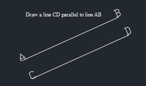
Object snap tracking (F11) works when object snap option (F3) is kept on. object snap tracks various points of object such as end point, mid point, intersection of two objects etc. they are also used to draw parallel lines and perpendicular lines with to respect to a given object.
You can get object snap and object snap tracking option under drafting settings for which you can press "DS" in command box. below diagram shows all the snap points which Autotrack uses.
While tracking any objects a "+" sign is displayed on tracking point with a green extension line with a "x" mark.
POLAR TRACKING:
In autoCAD ortho mode makes it possible to track in vertical or horizontal direction with increment angle as 0, 90, 180, 270. how ever we can set out increment angle as per our need for tracking using polar tracking option.
Polar tracking restricts cursor movement at user defined angles.
you can create or modify objects using polar tracking option when you want to trace a path along any specified angles.
You can also specify the polar increment distance in terms of units similar to angles. This feature enables you to create or modify any object at specific location and at specific distance.
As you move your cursor, a tracking line is placed as you come across any of your specified polar angle. The default angle measurement is of 90 degress, you have to use allignment path and tool tip to draw your object.
The default angles which is provided under autocad are 90, 60, 45, 30, 22.5, 18, 15, 10 and 5 degrees. if you want to use any other angle you can click at add angles option.
Polar snap restricts movement of cursor to incremental distance you have specified along the tracking angle. It won't restrict the movement of cursor other than specified angle. If you specify the increment distance as 5 units. It will allow you to make line of length 5,10,15,20,25 units and so on.
Note:As you know orthogonal tracking and polar tracking cannot be done at same time, similary reactangular snap and polar snap cannot be used at same time.
polar tracking option comes under drafting settings for which you have to press "DS" in command box.
STEPS FOR POLAR TRACKING
1. Press DS (Enter) in command box. it will open following dialog box.
2. Specify Increment angle, check polar tracking option on, click on track using all polar angle settings and then click OK
You get two options under Polar angle measurement. a. Absolute, b. Relative to last segment.
Absolute:
In absolute option as we have discussed in previous blog, it uses UCS as its reference and tracks in anticlockwise direction by taking X axis as base reference.
Relative to last segment:
In relative to last segment it considers last object drawn as reference axis.
TIPS TO USE AUTO TRACK (OBJECT SNAP TRACKING AND POLAR TRACKING):
- Use perpendicular, midpoint and endpoint snaps if you want to draw any object which is perpendicular to end point and mis point.
- There is no compulsion in keeping snap on, if u wish to draw tangent point to any circle or arc.
- Use object snap tracking along with temporary tracking points (tt), then specify a distance from which u have to create an object. A small '+' occurs on the base object from where tracking has been started also at the distance which you have specified. After tracking has been started a green dotted extension line is displayed along the tracking path. To remove the tracking point place the cursor again from where tracking has initiated.
- You must use direct distance entry once tracking has been started to draw on object with percision.
- To start tracking at any point keep cursor at the point from where you want to start path tracing and move cursor along the path you want to trace.
ABOUT SPECIFYING DISTANCES, LENGTHS, ANGLES.
While creating or moving an object you can specify the direction by moving along a tracing point and then directly enter the distance or length of the object. This method is known as direct distance entry.
To specify a line without entering co-ordinates, for second point move the cursor along the direction of tracing and then entering distance from the first point. You can also use inbuilt calculator of autocad for specifying the distance by which you have to move if any specific calculation is required.
You can use direct distance entry with all commands after locking object at any angle by tracking it orthogonally or by polar tracking, this is the fastest method and most efficient way to create any objects at any specified location, distance or angle.
Specify an Angle Override:
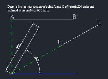
If you kept your ortho mode on and still want to make line at specific angle you can use '<' this symbol to specify angle in which you have to make line. Following command will help you to understand how to make line at specified angle.
Command: L
LINE
Specify first point: Click
Specify next point or [Undo]: <56
Angle Override: 56
Specify next point or [Undo]: 100
Specify next point or [Undo]: ESC
The angle you specify will lock the cursor at given angle even if ortho mod, polar tracking, grid snap is kept on. then you can specify the direction by moving the cursor and specify the distance or length which you need.
TRACKING METHOD:
This method can be used along with object snap, direct entry system.
To start tracing place your cursor at a desired point. object snap tracking will detect its respective point i.e. end point, mid point etc.
Move your cursor in desired direction and you will see, a green extension line known as rubber band line starts tracing your path with cursor.
If you want to create an object at desired distance from the reference point along tracked path, you can directly enter the numeric value.
If you want to create an object from the point where two lines (which are not intersected) will intersect in space, you can keep cursor at end point of first line and track in direction of second line, now keep cursor at second point and start tracing it backward, you will get new point where both lines will intersect. (see video for tutorials for better explanation)
TUTORIALS
 |
| Tutorial 1 |
 |
| Tutorial 2 |
 |
| Tutorial 3 |
 |
| Tutorial 4 |
Related Concepts:
Relates Task:
Related reference:


Comments
Post a Comment